Note: Photos and drawings referenced in this article may be viewed in two ways:
- Slide Show View: Click a small image in the photo set below. You can then move forward/backward in slide show view.
- Full-sized images: Click links in the article text or the links at the bottom of the page to view full-sized versions (in a separate page).
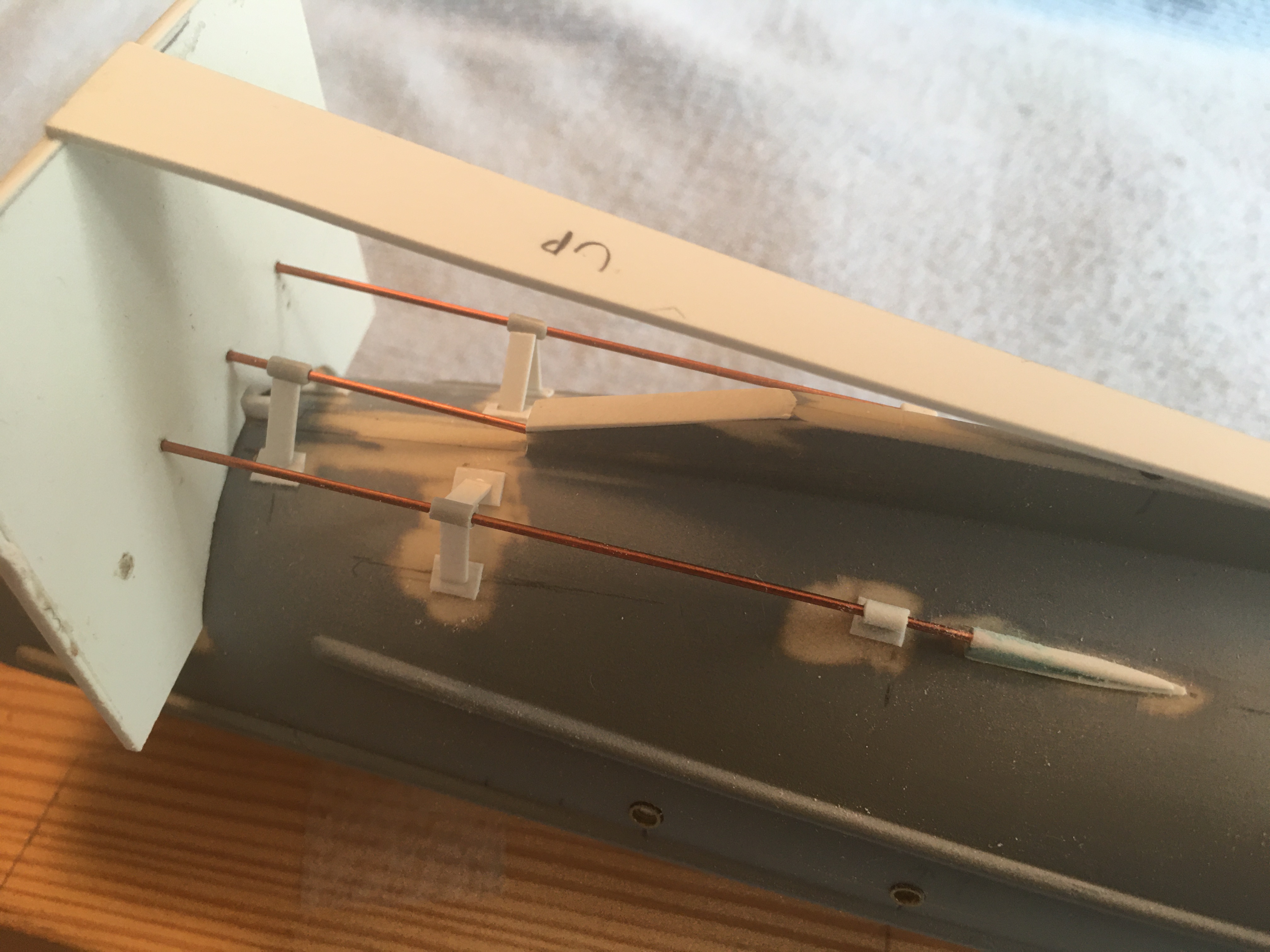
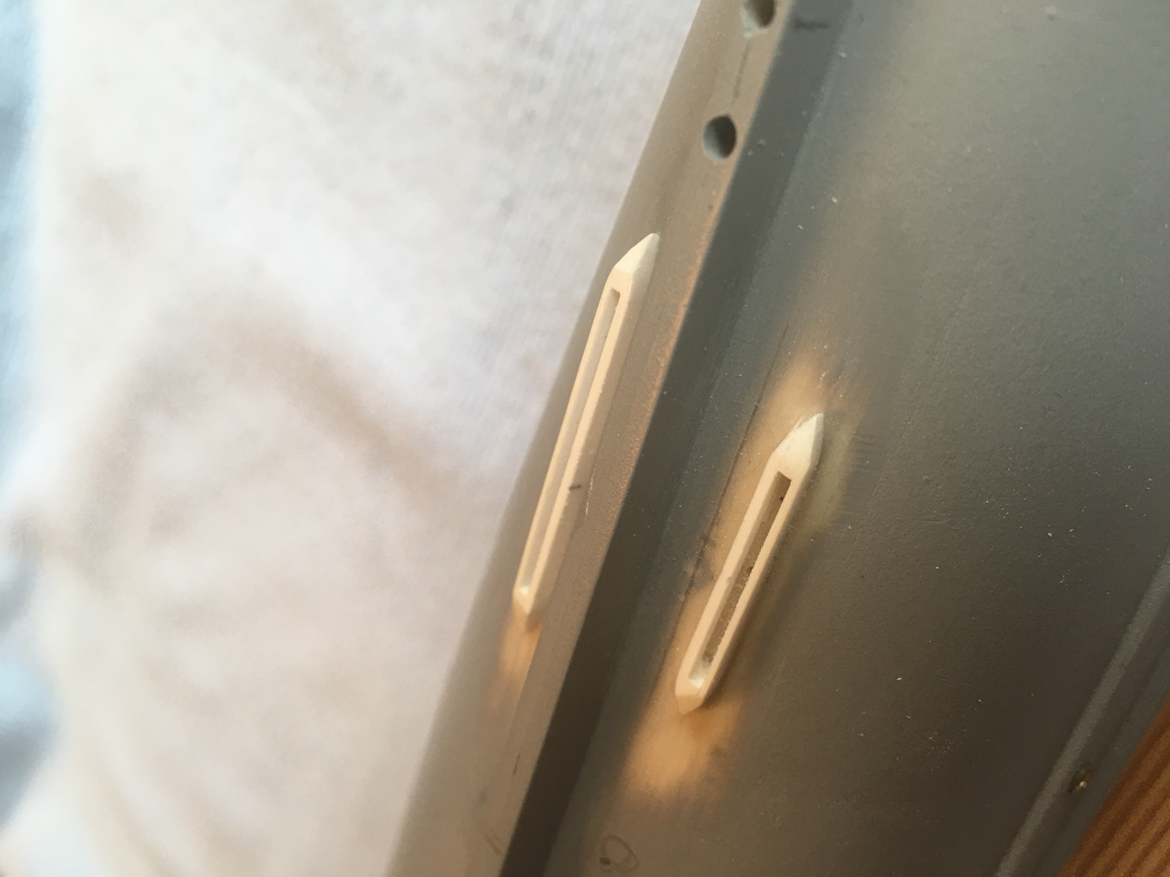
- 2020-07-02 - Two photos added: "One shows the rig I used to get the prop shafts aligned, while I re-built the struts. (The shafts are 14 gauge copper wire, which won't be painted, since the actual shafts had copper sleeves.) The other view shows the protective housings for the SC tubes."
Notes On Improving The Glencoe Sub Chaser Model
© John C. Hudock
2010
(updated March 2010)
This is really a nice model, in spite of the strange scale of 1:74. It’s one of the few “large scale” models on the market. The 110-foot wooden sub chaser (SC) was once quite popular with model makers. Several of the old (pre-WWII) ship model kit companies marketed solid wooden hull versions of this vessel in 1:48 scale (Boucher) or 1:64 scale (Marine Model Company).
This site, www.subchaser.org, has many photos and drawings of actual sub chasers, including “close aboard” pictures of various details, inboard and outboard profile drawings, and a deck plan. It is recommended that this material be carefully reviewed before doing anything with the kit.
Much can be done to improve the model just by giving it a good paint job. Specifically:
- Main deck and bridge (parts #7 and #15): A very light tan, like coffee with a lot of cream. BUT: original USN drawings clearly say that the deck was painted gray.
- Upper hull, all superstructures, masts, equipment, ordnance, boat, life rafts, stowage boxes, etcetera: Light "Navy" gray. Also, parts #8, #13, and #34 should be gray, as the USN drawings show them covered with painted canvas. Note that WWI USN gray was just that: a mixture of black and white (no blue). Testors’ Floquil brand “Classic Railroad Enamel” primer, #S-130009 (spray can; #B-110009 bottle), seems to be the best match available in hobby shops, but an ordinary spray primer such as Rustoleum brand is adequate. Look for a brand that has the least amount of blue. (Be sure you don't get a lacquer, as that will melt the plastic!)
- Lower hull: Red oxide (red metal primer, such as Rustoleum or Krylon brand).
- Boot topping (the black stripe above and below the water line), and the top of the galley smoke pipe (near stern, part #35): Flat black.
- Propellers (but not their shafts), bell (but not its bracket) and top of capstan: "Bronze"or "brass" color. "Jo Sonja" brand acrylic paint works well for this.
- The propeller shafts: A dirty copper color (they were covered with a copper “sleeve”).
- Note that the depth charges are not painted red, but Navy gray, same as the hull.
- Hull numbers: Flat white.
- All life rings: An “off” or "dirty" white.
- The box art shows the canvas covers on the railings and crow’s nest to be white, but in almost all of the WWI photos they appear to be gray, same as the hull. Gray may be more historically accurate, but white breaks up the monotonous gray of the hull.
- All paints should be flat, not gloss, except for the running light shields (see text).
- Wash all parts in detergent before painting, to remove any residue from the casting process, and don’t handle the parts with bare fingers before painting.
Some minor modifications to the kit are possible, and will considerably improve its looks but, before getting into that, first set the model up for a proper display mounting. Glue the two hull halves together, but before painting, carve two blocks of wood to fit snugly inside, about eight inches apart. The grain of the wood should run horizontally, 90 degrees to the keel. Epoxy these blocks in place. After the epoxy sets, turn the hull over and drill a clearance hole up through the keel in each block for a 1-72 threaded rod (.081-inch diameter; #46 drill). (Threaded rod is available from www.smallparts.com) Make sure these holes are perpendicular to the water line. Later, this system will securely hold the model to whatever base you choose. See drawing #1.
At this time you should also reinforce with additional styrene the areas in the hull where the prop struts, boarding steps, and rudder will be mounted. While doing this you will notice a number of lugs or “bumps” cast into the inside of the hull. When this kit was originally produced, years ago, it came with a motor. The lugs and bumps were for mounting the motor and batteries. See photo “A” of an incomplete hull.
Now, to the details, starting with the hull:
The protective cover for the hydrophone can be added, either built up from .020-inch styrene, or simply a solid piece, as it is placed down by the keel. See drawing #2
The kit supplied propellers are not very good. Consider getting cast metal replacements from BlueJacket Ship Crafters™. Three blade, 1/2-inch diameter. Two right hand (center and starboard shaft) and one left hand (port shaft.)
The plastic lifeline stanchions cast onto the hull halves should be removed. Replace them with 0.015-inch brass wire set in holes in the deck just inside the gunwale, not on top of the gunwale. They should extend .530-inch above the deck and be perpendicular to the water line. To provide a good footing for these wire stanchions, glue one or two strips of styrene inside the hull, just below the ledge for the deck. It’s best to add these strips before gluing the hull halves together. Drill the holes for the stanchions after installing the deck, but don't install the stanchions (or rig the lifelines) until the very last. Note that the lifelines do not extend all the way to the bow, as the kit’s assembly drawings show, but stop short of both bow and stern, as the box art shows. Note also that there should only be 22 stanchions per side, evenly spaced, beginning 1-15/16 inches from the bow and ending 1-3/16 inch from the stern. Lifelines on the model should be about 0.005-inch diameter. See drawing #3.
Lights (portholes) in the hull, deck houses, and hatches should be bored out and glazed with clear acrylic gloss medium lightly tinted with food coloring to a blue-green shade. First, bore out the lights. Behind each bored out light glue a piece of .020-inch styrene, painted black. After painting the outsides gray, put a drop of the gloss medium in each light. Capillarity will hold it in place. (Similarly, the face of the search light (part #54) can be bored out, the hole painted silver, and then filled with gloss medium.)
Bore out holes in the hull to represent the engine exhausts. There are three: two to starboard and one to port. There is one each, port and starboard, 65 feet (10.5 inches) back from the bow. There is one to starboard 74 feet (12 inches) back from the bow. As designed, these exhaust holes were about one foot (.16-inch) below the waterline. Later in the war they were moved up to just below the rubbing strake. Inside diameter of the exhaust was 6 inches (.08-inch). The auxiliary engine exhaust is 69 feet (11.2 inches) back from the bow, and one foot (.16-inch) below the waterline. Its inside diameter is 2.5 inches (.034-inch).
The lower hull is now ready for painting. Unlike many plastic models, this one does not have the water line as part of the hull casting. You will have to “strike” the water line per drawing #15A. Note that the boot topping straddles the waterline, and the top edge sweeps up towards the bow in a gentle curve.
On both sides of the hull there are two gangways: places where the lifelines could be removed to allow easy boarding. The top of the gunwale is protected by a sheet of brass at these points, and there is a step with a brass kick plate behind it on the hull 1/4-inch below the gunwale. Make the plates of .005-inch styrene painted “brass” (or use brass foil) and the steps of 0.010-inch brass wire. The lifelines at the gangways are small chain, not wire, but the smallest chain that I have found commercially is from Model Shipways at 42 links per inch, which is what the anchor chain should be, and that is still a bit oversize for that application. Therefore, for the chains at the gangways, try this:
1) Twist two strands of very fine (.005-inch) wire together.
2) Paint with semi-gloss black.
This will simulate chain covered with a canvas “sleeve,” which used to be common practice on USN ships. See drawings #3 and #4.
(Remember: affix the stanchions and lifelines last.)
The big white hull numbers on the bow were typical, and show up prominently in old photos, but painting these cast-on letters can be tricky. Don’t try to do it with one coat. Use a very dry brush and build the paint up slowly. An alternative: sand the entire hull smooth, and re-number to suit the particular SC modeled.
Now the model is ready to be mounted on its display base or, if you wish, on a temporary “working” base of scrap plywood. Epoxy lengths of 1-72 threaded rod in the holes that were drilled earlier in the hull blocks, and secure the hull on its base with a nut and washer.
On a model this big the plastic deck (and bridge, part #15) can be sanded flat and individually planked with real wood strips. Note that on the deck casting there are a number of small circles molded in the plastic. These represent various scuttles and filling caps, and should be painted gray. If a wooden deck is made, these must be represented with small circles of styrene, or short pieces of brass wire, set flush with the deck. There are also a number of places where eyebolts should be installed. Some are on the main deck. These should be made from .010-inch brass wire and installed before the deck is glued in place. See drawing #5.
Pilothouse joinery varied considerably from yard to yard. All of the walls of the pilothouse as supplied with the kit are simply plain (and thick) plastic slabs with square holes for the windows. Photos and original plans show window frames, drip caps, and sills, as well as some with trim molding below the windows. At this scale, moldings can be nicely done with fine (0.005-inch or so) wire. Frames, drip caps, and sills can be cut from 0.010-inch styrene, with clear styrene “glass” sandwiched between the frames. Also, the pilothouse is large enough and there are enough windows in it to allow the interior to have some detail. A wheel, binnacle and engine order telegraph can be added, as well as a chart table. Note, by the way, that the open bridge deck is about 12 inches (3/16-inch) higher than the “floor” of the pilothouse. See drawings #6 and #7.
The aft side of the pilothouse has the outline of a door (port side) and the outline of a ladder (starboard) cast in. The cast-in ladder should be sanded off and replaced with one made of brass or plastic, either a vertical pipe ladder or an inclined wooden one. The door may be left as is, or cut out and modeled open. See drawing #8. Photos show the door hinged on either side. A small, round-head pin, cut off, can serve as a door knob, opposite the hinges. (As originally designed, there was no aft side to the pilothouse. Just a curtain. That would have been interesting in a North Atlantic winter!)
Drawings and photos show an antenna lead-in just forward of the pilothouse. It is protected with a half-cylindrical wire mesh safety shield about 12 inches or so in diameter and four feet high (5/32 by 9/16 inch). Fine photo etched screening can be used here. The lead-in itself is a single wire which branches to four leads about five feet (one inch) below the aerials.
On the model the railings of the open bridge are represented by thick plastic (parts #40 and #41), giving the impression that they are solid, something like a steel splinter shield. Plans show a pipe railing of three equally spaced rails 36 inches high (.495-inch on the model). Photos always show these rails covered with a canvas windscreen. The box art shows a railing on the roof of the pilothouse, which should also be 36 inches high. Photos and plans show one to three rails. These railings can be built up of 0.015-inch brass wire and covered with tissue or fabric “canvas,” painted either Navy gray or dirty white. The "crow’s nest" (part #70) is also a pipe frame covered with canvas. The box illustration shows all this correctly.
About 1/4-inch forward of the aft end of parts #40 and #41 there should be vertical posts about 0.040-inch in diameter. They should extend above the top of the rails about 1/16-inch. These are the mounts for the Colt-Browning .30 caliber machine guns. See drawing #8. Note that this is not the .30 caliber Browning LMG of WWII. A Lewis gun could also be used there. A nice touch is to add the quarter-circle gratings that give extra foot room to the machine gunners. (See the deck plan at the SC web site.) Off-the-shelf photo etch can be use for these. If you do this, you will need to extend the railings of the open bridge back to the aft edge of those gratings.
Two life rings can be made and hung on parts #40 and #41. Another pair could be hung on the lifelines, well aft. A single life raft may be added lashed on edge aft of the two ventilators on the engine room trunk. See drawing #10.
On the pilothouse roof there is an arrow, much like a weather vane. At the time the molds were made, the construction of this item was not really understood. For a better representation, first cut a new arrow from .010-inch styrene, per drawing #11. Next, carefully cut and file away the existing arrow, leaving only the small wheel. Glue the new arrow over the wheel. The side of the arrow with the wheel is the “back,” and is painted gray. Documentation from the period indicates that the color combination for the front of the arrow was: the head white, the shaft yellow, and the “feathers” red.
In addition to the arrow, USN drawings also show a peloris on the roof, mounted on the centerline, about two feet (5/16-inch) forward of the aft edge. A whistle can be added at the aft edge, either on the mast or near the starboard aft corner. See drawing #12.
The 3”/23 main gun is one of the weak points of the kit. A scratch built replacement would be best, but even some minor additions to the existing part can help. See the USN gun photos and drawing at Todd’s web site. In the neighborhood of the main gun, photos show a variety of small stowage boxes. Outlines for two such boxes are cast into the model’s deck, but not included as separate parts. Make two from styrene. They are about 7/32-inch high.
At the apex of the angle of the spray shield (part #39) just forward of the 3”/23 gun there is cast into the deck a low triangle. Some drawings and photos show this area to be covered
with fore-and-aft slats that formed a low “crib” for stowage of a “suction hose,” but others don’t show it at all. If you use the plastic deck, paint the triangle gray, or cover it with plastic strips to represent the wood slats. If you’re laying a wooden deck, build up a “crib” from individual pieces. In this same area you can add another smoke vent similar to part #35. It’s for the coal stove in the crew’s berthing area.
Other deck details represented on the kit’s plastic deck, but not provided as separate parts, are four cleats and two towing bitts. These can be fabricated from wire and plastic and added, if desired.
The A-frame antenna mast (part #46) at the bow is oversize (too thick), and would look better if re-made out of 0.020-inch wire.
The kit’s anchors have the stocks cast on. Scrape these off and add separate stocks made of wire. The balls on the stocks can be built up with white glue or solder. Note that there are two sizes of anchors: smaller one (150 pounds) to starboard and larger (250 pounds) to port. There should be three wood “pads” for the flukes and stock to rest on.
While working on the ground tackle (the anchors and their related equipment), add the chain trough (two sections) for the anchor chain to ride in on its way to the capstan, to port of the center line. Two pieces of Evergreen brand styrene 0.060-inch channel stock will do. Also add a chain pipe just forward of the capstan, starboard side. See drawing #13. The starboard anchor should have a chain attached, about 42 links to the inch. Chain should run from the anchor, over the side, back through the bull nose fairlead in the bow, around the wildcat at the base of the capstan and then down the chain pipe. Note that the capstan as supplied with the kit does not have a wildcat (a sprocket-like device that handles the chain), but one is needed, as the anchor chain did NOT wrap around the barrel of the capstan. The kit capstan looks something like “A” in drawing #14.. It can be modified per “B” to provide a dummy wildcat. There is a good photo of this on the SC web site under “Close Aboard.”
Photos show that a windlass was more common than a capstan. This is what is shown on the deck plan on Todd’s web site. Note that the chain trough should lead to the wildcat on the windlass, usually on the starboard side. The chain pipe was usually integral to the windlass mount, below the wildcat and a bit forward of the windlass axel.
The wherry (dinghy) should either be fitted with a "canvas" cover (per the box art) or extensively re-worked. The hull is too thick and should be thinned down. Part #19 should be discarded and thwarts and other interior details individually modeled from styrene. One could also use the kit wherry as the starting point for a plaster form, and scratch-build a lap-strake boat from strip styrene, as shown on attached photo “B.”
Beneath the wherry is a skylight, part #16. Three windows each side. These should be “glazed” with clear styrene and have brass safety bars across them.
The steps cast on the mast are over size and should be sanded off and replaced with wire (0.006 – 0.010-inch). For strength and scale appearance, consider replacing the plastic masts and yards with brass wire and tubing. Also on the mast: the boat davit (part #73) is stepped too far up the mast. It should join the mast about 7/16-inch above the bridge deck.
Parts #17 are stowage boxes with recessed panels, not windows, in case the instructions don’t make that clear. The ones in the kit often have severe casting dimples, which will have to be filled in with hobby putty.
Replace all navigation lights with transparent plastic: red, green, or clear, as appropriate. Toothbrush handles are a ready source of transparent clear, red, and green plastic. Note that the inside surfaces of the running light shields (parts #56 and #57) are painted gloss red (#56) and green (#57), respectively.
No stern depth charge drop racks are provided in the kit, and the USN drawings don’t show any, but accounts clearly state that charges were dropped as well as being fired by the Y-gun. Some photos show racks made from 2 by 4 or 2 by 6-inch timbers, and accommodating one or two charges. Another photo shows a longer rack on the port side, aft, and yet another shows a sheet metal two-charge rack, and still another shows a single 10-charge rack on the centerline made of angle iron. Note that a 300-pound depth charge is 27-5/8 inches long and 17-5/8 inches diameter, and the ends are concave, so the firing mechanism doesn’t protrude. BTW: No photos have yet been found * showing spare depth charges or arbors for the Y gun stowed on deck, so you may want to remove the four that are near the Y-gun and use them on the drop rack(s) at the stern. See drawing #15.
The wire cables for the rudder run aft from the pilothouse, port and starboard. Drawings show them running either outside the gunwale or inboard of the lifeline stanchions, with a few fairleads to guide them. Where they exit the pilothouse they are covered with a piece of sheet metal so crewmen won’t trip over them. The cables should be .006” or .007” diameter on the model. On a related matter, the rudder quadrant is shown reversed on the kit’s assembly drawings. The arc should face aft. Part #68, which covers the quadrant, can be a grating. If you make gratings for the machine gunners, make one for here, too.
Some comments on flags: A model displayed on keel blocks looks best if the flags are flown as if moored: jack at the bow and national ensign at the stern. If the model is displayed on two pedestals, the flags can be flown as if under way: national ensign only. On the SCs, the national ensign almost always flew from the short mast on the aft deckhouse, whether moored or under way. A commissioning pennant may be flown from the main mast in both cases.
Rigging: See drawing #16. One of the more common errors that ship modelers make is to rig their models with line that is too thick. This really detracts from the overall impression. Some guidelines for this model, at 1:74 scale:
Use fine thread, in the diameters noted below. Gray for the standing (supporting) lines, a "copper" color for the aerials (perhaps highlighted with a bit of light green "verdigris") and very pale tan for the flag halyards and any other "running" rigging, such as the anchor davit and the davit for loading depth charges onto the Y-gun, which have tackles. A suitable material is the fine thread used by fishermen to "tie" (that is, to hand make) their fly lures. Insulators for the aerials can be simulated by short pieces of plastic insulation cut from fine electronic hook-up or "wire wrap" wire from Radio Shack®.
Specific line sizes:
Life lines and wire stays: 7/16-inch diameter = .005” to 006” on model. Use gray thread.
Flag haliyards: .006” or .007”, pale khaki color.
Tackle on anchor davit and boat boom: .008” or slightly larger, pale khaki
Aerials: .004”, copper color
Aerial lead in: .008”, black
Before using the thread, pull it through a chunk of beeswax to lay down the knap.
Note on how to measure thread: On a smooth dowel or pencil, snugly (but not tightly) wrap twenty turns of the thread in question. Slide the turns together, so they are all touching. Measure the length of dowel covered by the twenty turns. Divide by twenty for the thread diameter.
* Editor's Note: Christopher Olson notes that it does look as if there are some depth charges on the deck in the third photo of SC 181 on this page. I suspect this is a "one-off," and agree with Jack that depth charges shouldn't be shown stored on the deck.